

|
|
|
Fire Station Alerting System Design [This page is a work-in-progress. The design works every day at our new stations. I just need to do more work on the documentation. Square Brackets generally indicate things I need to complete] Fire Station Alerting appears to go by a few different names. Depending on where you're located (and your age), it could be called "Recall" "RingDown" "Alert" "Klaxon". I'll call it Recall. If you work for a volunteer fire department, you might be interested in this design. Some of my design goals:
First, let me remind you that you got this idea from some web site on the Internet. I do not claim that this will meet your needs. Use these ideas at your own risk. There is no warranty, expressed or implied. It is up to you to decide if it meets your needs and expectations. Do not attempt this installation if you're not technically competent. I make no claims that it will meet your department's standards or meet any local or national codes. My design is specific for the Department I work for. However, much of what I have done can be adapted to other systems. For example:
Bill of Materials
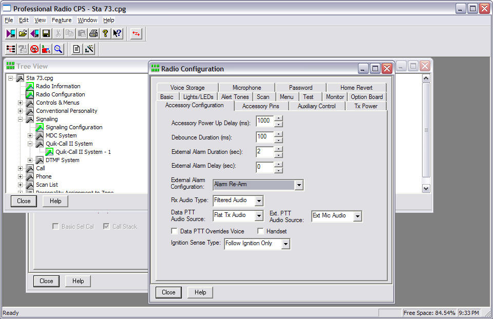
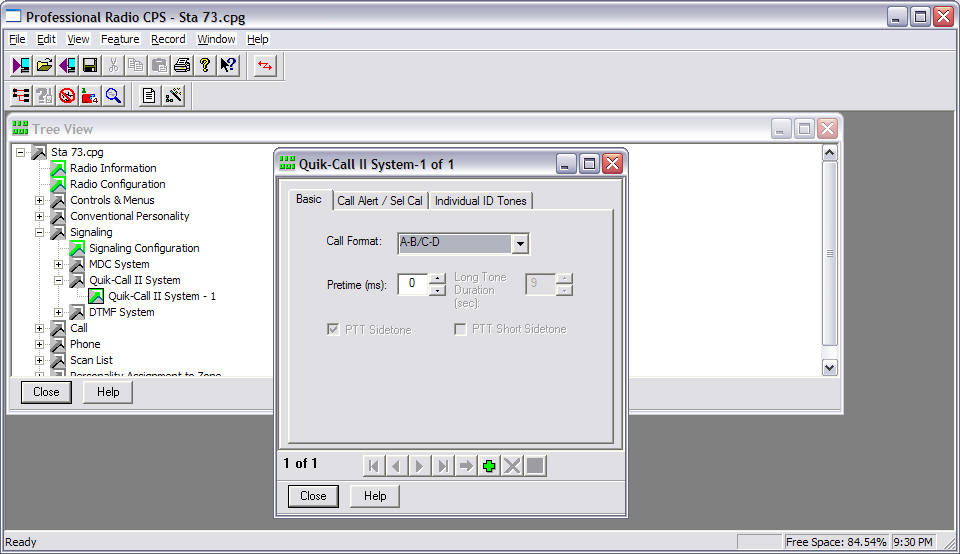
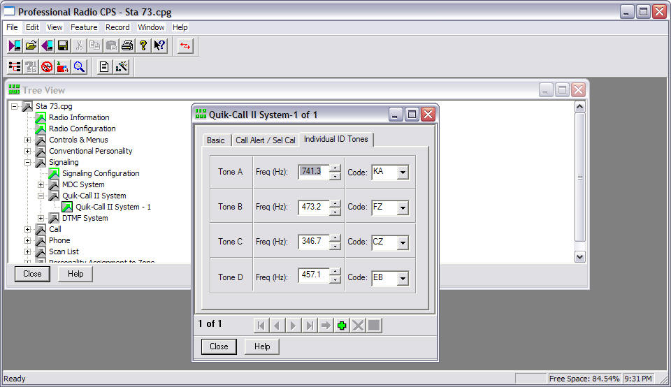
I'll assume you already have some sort of over-the-radio alerting system in place today. A couple tones or a burst of tones followed by the dispatcher's voice. If you have this, this design could be used to add another fire station or to replace an aging system at an existing station. It could also be a way to add another alert for a station, for example, in a detached exercise facility near the station, but too far to cable to. The brain to this system is the Motorola CDM1250 Radio. Built into its programming is a external alarm decoder. This is where the decoding happens. The radio stands by, constantly listening to your dispatch channel, even when the volume is turned down. When the right type of codes are heard, and they're exactly the correct frequency (pitch) the radio will close a contact (electronically flip a switch). You connect to this contact closure through a 16 pin connector at the back of the radio. If your department uses another type of radio, see if it can decode your department's type of alerting. If it can provide a short contact closure output when the tones are sent over the air, then this project could work for you. I've only done this with the Motorola CDM1250 radio. You, or your radio tech, will need to program the radio to decode the right set of tones and configure the radio to give this contact closure. The following screen shots from the Motorola radio programming software shows the steps for our radios. (click on the image to see it larger, then click it again to see full size).
You'll likely need to trigger on two different sets of tones. One is specific for the station, the other is an all-call that would trigger all the stations on the channel, or all stations in a Battalion or Division. The radio can stand by for two different sets of tones. If you don't need to listen for an all-call in your application, you might be able to have two alerts, for example, one for the Suppression, one for the Rescue. The 'switch' inside the radio really isn't a switch. It's a tiny transistor. While it logically works like a switch, it has some important limitations. You can't use it to directly turn something on and off. It can only switch low current at low voltage. You'll damage the radio (and maybe yourself) if you try to use the radio to directly turn the lights on and off. You have to use an intermediary, a relay, to actually do the heavy lifting. This design uses 3 relays. Once the programming is done, you'll need to make connections to the radio via the accessory connector on the back. It's a 20 pin connector that you build by adding female pins as needed. If you want to test the radio before you continue, put a volt ohm meter across the contacts. It should show a short for 2 seconds after your dispatcher sends this station's tones. Thanks to Batlabs, a great Motorola radio resource, here's the layout of the connector. The connector you'll use has only 20 pins. When you plug it in, center it so pins 17-20 are showing.
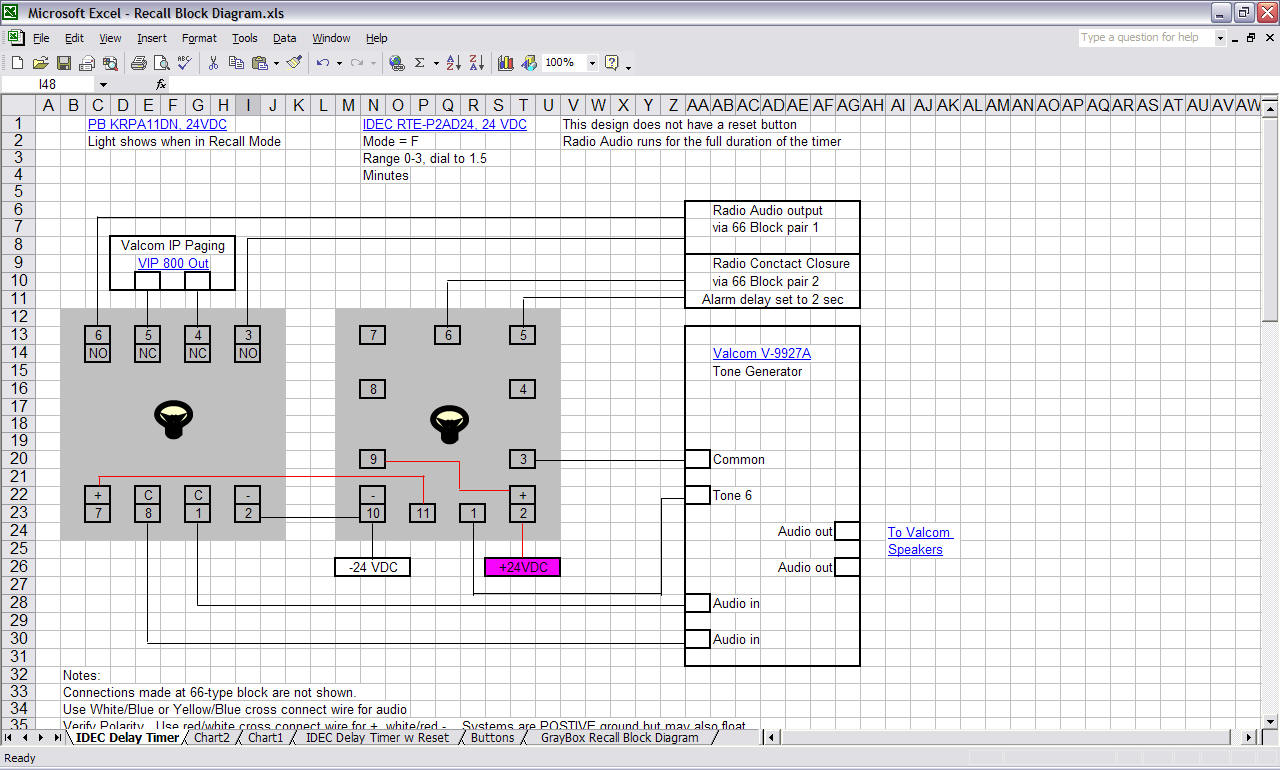
If you're wondering why the odd pin number layout, it's because the older generation of these radios, called Maxtrac, only had 16 pins. The CDM series uses this connector so the same line of accessories could be used. That was very nice of Motorola. Attaching the wires to the female pins may be the most tricky part of this operation. A special tool helps a lot. It is possible to use needle nose pliers and solder, but expect to need a magnifying glass, steady hands and some patience. When the pins are attached to the wires, you think insert them into the back of the connector. If the connector is already in place, you just slide in your new wires where you need them. If you want to learn much more about the CDM line of radios, here's Batlab's page. How long do you keep your speakers on? With this design, this is flexible. The first timer is very much adjustable. We'll be using mode F in this timer, with the dial set for 0 to 3 minutes. In our department, we aim for 1.5 to 2.0 minutes of recall audio in our stations. But your actual time may vary. For example, complaining neighbors may make it shorter, a single unit station may want it longer. The way you tie this all together is up to you. There are no hazardous voltages in this design so you can use regular telephone wire. Our standard is CAT 5 cabling to all locations in a fire station. So the radio audio and contact closure connect to a 8 pin RJ45 cable, then plug into the wall. In the telecomm closet, another cable connects the relays to the patch panel. Regular 22 gauge solid telephone cross connect wire is used between the blocks and between the relays. Stranded wire should be used where the cable needs to flex, like between the wall and the radio. I use red/white wire for the 24 VDC wiring and white/blue for audio. Keep in mind you're dealing with Direct Current here. It does matter which way you connect the wires, plus and minus. For historic reasons, telephone related systems, like Valcom, use POSITIVE ground. If you're used to vehicle wiring you expect negative. When you see two connections "24 VDC" and "GRN" the positive goes to GRN. It takes some getting used to. The positive side doesn't NEED to be grounded, but it may be. In many systems, I see both floating. The mostly red wire in my installs is the positive wire. Here's how the equipment is connected. The relay on the left switches between the regular overhead page and the recall audio. Double Pole, Double throw. The audio is balanced, so both leads need to be switched together. The center relay is the time delay. It energizes the left relay for a set time after the contact closure comes from the radio. The relay on the right is the reset relay. In it's normal mode, it passes power to the center relay. But when the reset buttons are hit, this relay drops power to the center relay. That immediately stops this relay from triggering the left relay. As the reset button is released, the center relay goes back to standby mode.
Easier version that does not include the Reset Buttons. The text above still explains how it works, just ignore the parts about the right relay. The center relay always gets power and always runs for the set duration.
If you want, you can mount the relay jacks on the wall, or if you're worried about tampering, you could mount them in a locking box. Locking them up hurts when you're trying to work with a firefighter over the phone while you're troubleshooting. There are indicators that can give you a good idea of what state the system is in if the person you're working with can see them. Valcom Tone Generator Jumper Settings
Alert Tone Selection. Valcom has samples of all the tones on their web site. Choose carefully. Yes, some will wake the dead. But there have been studies that have shown that an alert that's too loud, too sudden, can cause irregular heart beats. We use the 4 chimes generated by using screw #6 and P3 IN. About the speaker system. Again, what you have in place may dictate how you proceed. If you're starting from scratch, we really like the Valcom approach. Rather than a huge amplifier to cover the whole station, Valcom uses a small amp in every speaker. This gives us much more flexibility. Adding a new speaker or horn is easy. You just need to verify that your power supply is big enough. If not, you can add more power supplies. We use the same speakers for both overhead paging from the phone system and recall. One of the relays in this design makes sure the recall gets top priority. You won't be able to make an overhead page during the recall time. About the wallplates I specified. They're hard to find and expensive, but I wanted a heavy gauge stainless steel to hold up well over the years. These buttons are going to take some abuse as their hit on the way out the door. The ones I use are really solid feeling and should survive years of smashing. Since you don't want to miss a call, put all of this, the radio, the Valcom power supply, everything, on a UPS. Make sure it will run everything while your station generator starts up and gets stable. Some tips if you're wiring a new station: Electrically, you can loop the speaker wiring. Each speaker needs two twisted pairs, one for the sound, one for the 24 VDC. Everything can work in parallel. But don't. You'll regret it later. Instead, home run each speaker back to the telecom closet. At least keep each room separate. Some day, you may want to alert the Rescue dorm separately from Suppression. Or turn off the outside speakers after 22:00. Having a cable coming back from each will make changes like this easy later. While 2 pairs are required, run a 4 pair CAT 3 cable. One pair can be used to run your low voltage red LED lights. Placing the lights next to the speakers will be easy. Some places use the last pair for a hotline ringer. A ringer on the wall of the bay near the speakers will be easy to hear. CAT 5 cable could also be used, but it's more expensive and not needed. When the cables get back to the telcom closet, punch them down on split 66 type punch blocks. 4 pairs from each speaker on the right side of the block, then the next 4 pairs and so on. On the left side of the block, using the non-cut side of your 66 punch tool, loop a red and white cross connect wire to all the power pairs (say white/brown). Complete the circuit by inserting bridging clips down the middle to connect the left side to the right side. While this is a little more work now, you'll thank me when you're trying to track down a short 3 years from now. You just remove all the power bridging clips then put them back on one at a time until you see the power supply light go off. Without the bridging clips, you would have to remove the looping cross connect wire and reinstall it one at a time. If you already have one of the older 70 Volt line PA systems, most of this design will still work. You'll just need to feed the signal into an input on your existing amp. You may also need to trigger some relays in your current PA with the relays in this design. I've done it at a station where two departments with totally different recall systems shared a station. But each installation will be so different I can't help you much more that to tell you to add a relay if you need to. It's modular and expandable. The very same Valcom tone generator can also act as your door bell. Since it has multiple inputs, it can be triggered by a few different devices. Just connect your doorbell push button to screw "Tone 2" and the common screw. This means your doorbell will be heard throughout the station and you'll never miss another Blood Pressure check. (oh Joy.) Disconnect the old mechanical doorbell and be sure to remove the 16 VAC transformer too. You only need the momentary contact closure of the door bell button. For the doorbell I used a button similar to the type used for reset. Yes, a bit overkill, but it is lighted green and looks impressive at the door. Additional Parts for the doorbell option:
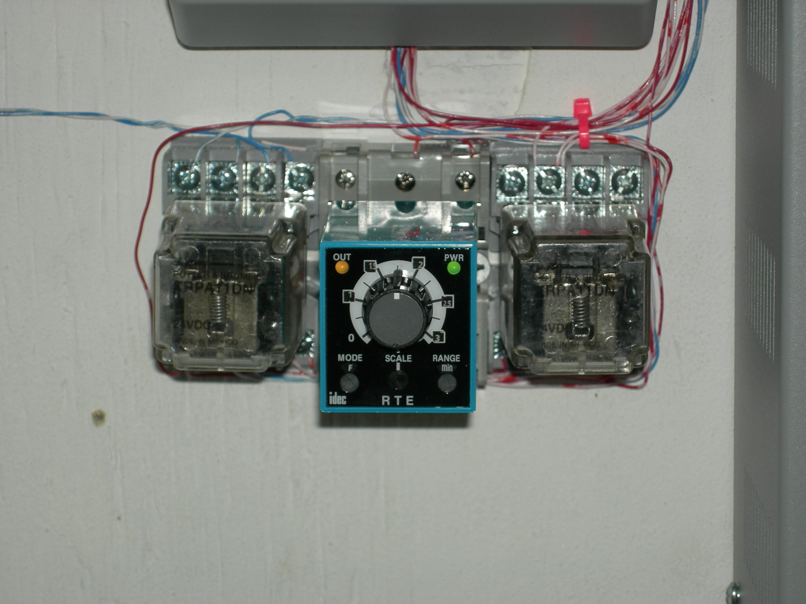
Some typical installation pictures. Click on the images to see them full size. The 3 relays of the reset-able system. Speaker DPDT, Timer, Reset DPDT.
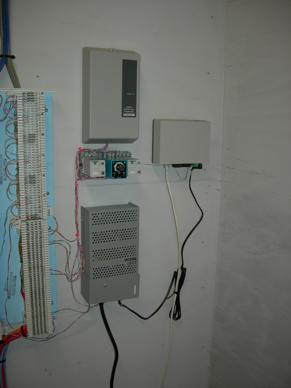
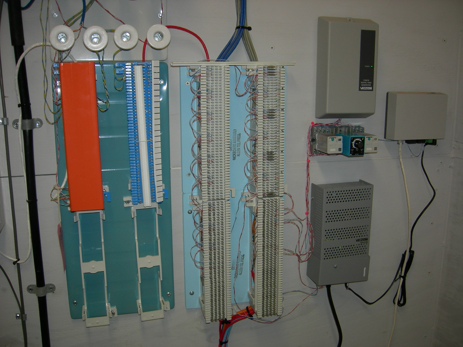
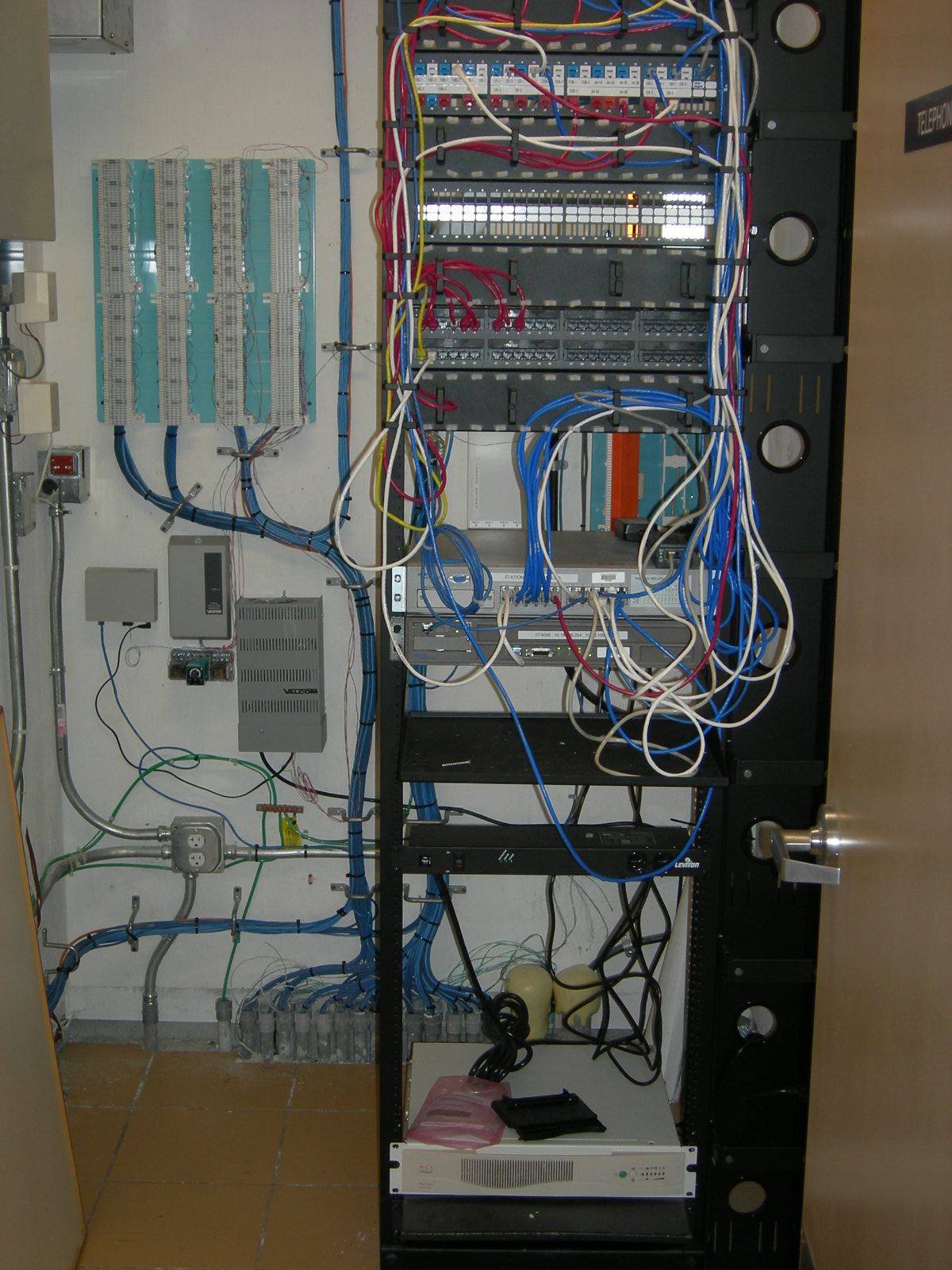
Showing the Tone Generator, Relays, and Power Supply. The gray box on the far right is Overhead Paging over IP and is not part of this system. If you want you speakers to also handle your overhead paging, then connect your source to the normal input (non-energized) input of the left relay, pins 4 and 5. This picture shows the Telco 21X telephone demarcation point (orange cover) and the PA speaker punch blocks (light blue background).
The Radio UPS, 12 Volt Power Supply, and Motorola CDM1250 Radio in the watch office.
A full view of the Telecom Closet in the Fire Station.
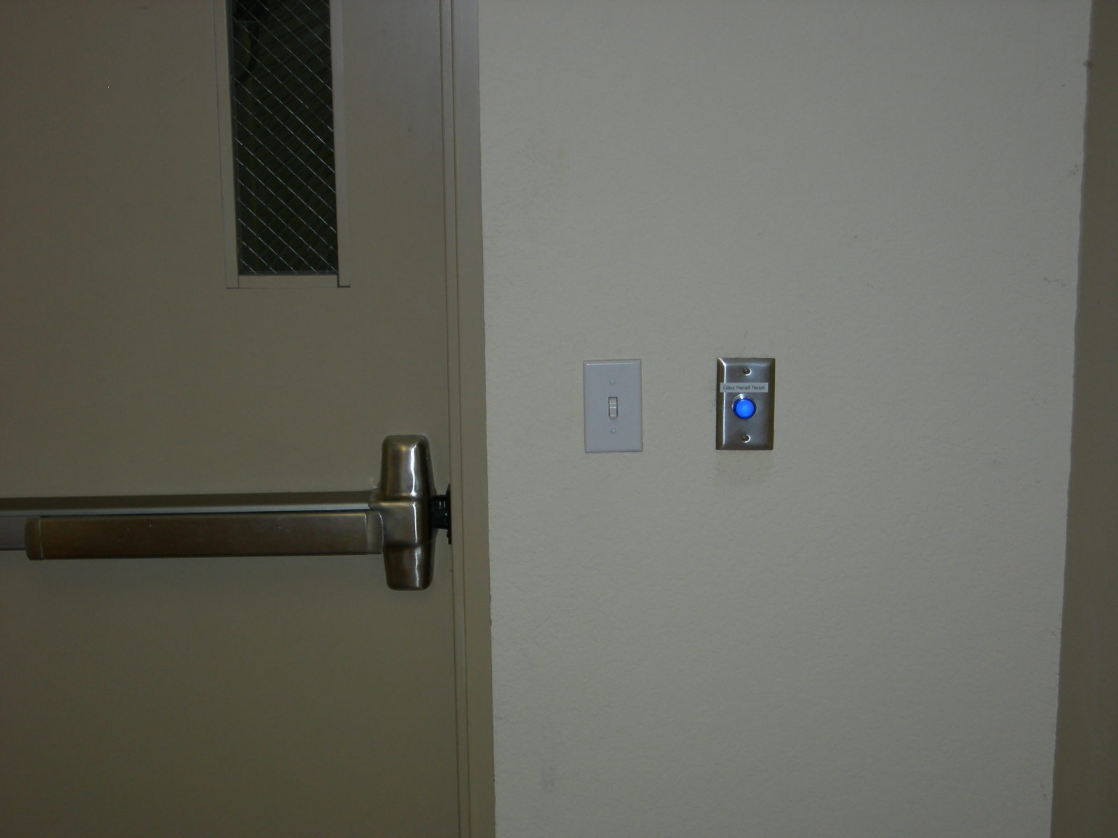
Lighted Reset button next to the door to the Apparatus Bay. The blue LED in the button is only on while the Recall is active. About 1.5 minutes or until this button is pressed. Pressing it lets the other crew in the station get back to sleep faster.
Please let me know if you have used any of this design in your fire station. Let me know what you liked and what you didn't use. I would like to add your comments here so others can learn from your experience. Thanks. Last update to this page: 03/01/2008 |
|